
Oral Presentation at APS Centennial
Session UB04 - Instrumentation for Nuclear Physics
Yury Blyakhman, Burton Budick
New York University, Physics Department.
BRAHMS Collaboration.
March 1999
The Broad RAnge Hadron Magnetic Spectrometers experiment (BRAHMS) is designed to measure charged hadrons over a wide range of rapidity and transverse momentum for all available beams and energies in experiments at RHIC (Relativistic Heavy Ion Collider), Brookhaven National Laboratory. Figure 1 shows a perspective view of BRAHMS detector system. One set of these detectors, called Beam--Beam Counters will be employed to characterize collisions from a global perspective and to provide an initial trigger, and permit a rapid estimate for the collision point (vertex location, marked as pink on this Figure).
Detectors were designed and tested using computer simulations with the help of the CERN code GEANT. FRITIOFF and Venus models were used as an event generators, in order to study detectors response with respect to different parameters. Results of these simulations, plus studies of the detector's prototypes in a test beam can be summed up as follows.
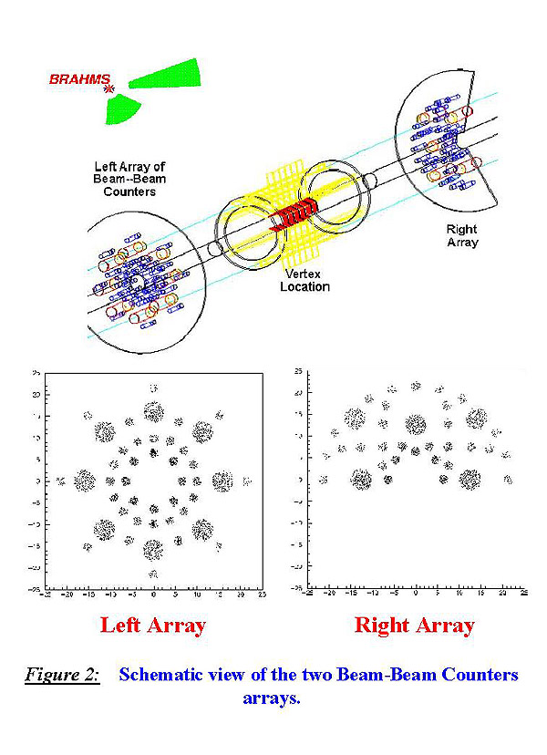
Figure 2 shows the enlarged side and front view of the two Beam--Beam Counters arrays. As one can see on top, they are located some distance backwards and forwards of the beam vertex and can be moved closer or further away at will. Each detector consists of Cherenkov radiators, glued to the photomultiplier tube. Phototubes diameters are 19mm or 51mm with 4cm long or 3cm long radiators respectively. Bottom pictures show front view of the detectors; dots on this picture represent the expected charged particle hit density. The right array has reduced azimuthal coverage because of the magnet D1 (see Figure 1). It was partially compensated by higher spatial density of modules in the right array.Also, several counters in both arrays are located at the same distance from the beam-pipe, which should provide better precision and might help in case of any malfunction diagnostics.
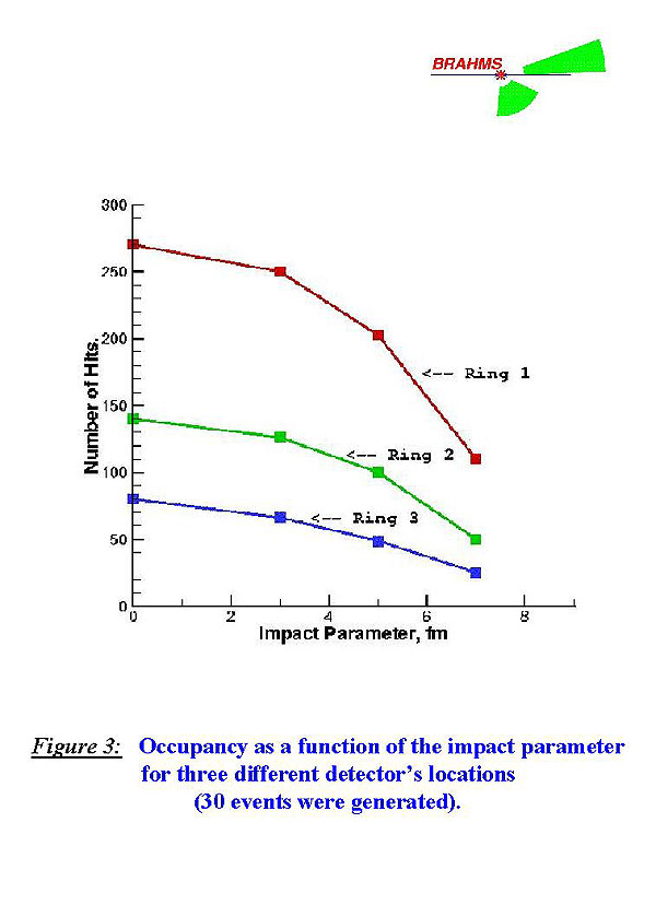
Detector's geometry, phototubes size and length of the UVT were specifically designed for the detection of both kinds of collisions (central and peripheral) and best timing. The ultimate goal was to get at least one hit in both arrays in a case of the most peripheral collision. Figure 3 shows occupancy (number of hits in all detectors in the Left Array) as a function of the impact parameter for three main detector's distances from the beam-pipe (different ``Rings'' of small detectors in Left Array). As one can see, even the most outer detectors in ``Ring 3'' will pick up at least one event in a case of the most peripheral collision (30 events were generated).
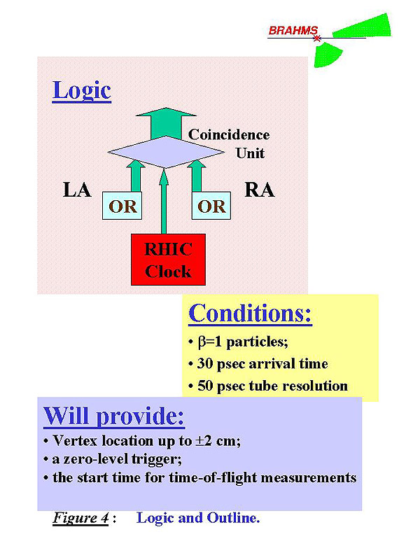
Basic experiment logic and outline is given on Figure 4. A module will trigger when a Coincidence Unit receives three signals at the same time: from two OR units, related to each of the two arrays (Left and Right); and a signal from the RHIC Clock, saying that beam entered the Interaction Region. The OR unit will click if at least one particle hits any of the 44 tubes in the Left Array simultaneous with one hit in the 36 tubes of the Right Array. So, good timing of an interesting high multiplicity event, will be produced if at least one charged particle with \beta=1 strikes the active area of the module in every array and arrives within 30psec of the arrival time expected for it. Tubes alignment and an intrinsic time resolution for each tube of 50psec, will make possible fast coincidence between arrays which will serve to identify the reaction vertex to +- 2cm. By these means, Beam-Beam Counters are designed to provide:
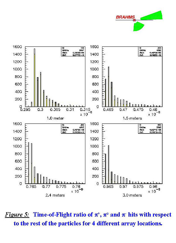
Figure 5 shows Time-of-Flight ratio of Pions with respect to the rest of the particles for four different arrays locations. It illustrates the time resolution, our counters can provide. Studies of pions multiplicities and serving as a zero-level trigger, implement having as much pions as we can and the least possible number of secondary hits in our detectors at the same time. As one can see, number of pions is decreasing with distance from the vertex, as well as the amount of secondary hits (\gamma's were excluded from this plots). Distance of 2 meters were chosen as the best possible one, providing time resolution of about 50psec.
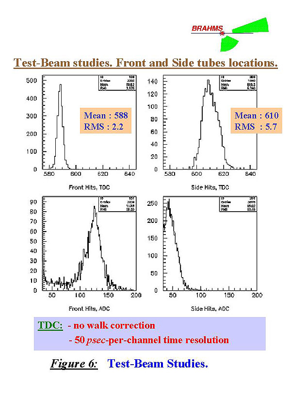
Figure 6 shows real-time studies which were made with two assembled phototubes, (with good wrapping and UVT attached) in a test beam of pions. Tubes were tested in two different configurations: facing the beam and sideways to it. TDC and ADC spectra are represented here. TDC spectrum is given without slewing correction. As one can see, width of 2 channels, assuming time resolution of 50psec-per-channel will give us required resolution of 50psec after walk correction. Bottom row shows ADC spectra, pretty clean and giving us a resolution of somewhat 25\%.
From mentioned above, it is clear, that Beam--Beam Counters will be able to serve as a zero--level trigger for BRAHMS. As of today, all phototubes have been tested and are ready to work; mechanical stand was designed and is being manufactured at BNL shops. Beam--Beam Counters are expected to be fully operational by the time of the Test Beam in July 1999.
to the Beam-Beam Counters Public Page