Reflection Current Studies with AGS CNI Chamber 8/14/02 - 8/19/02
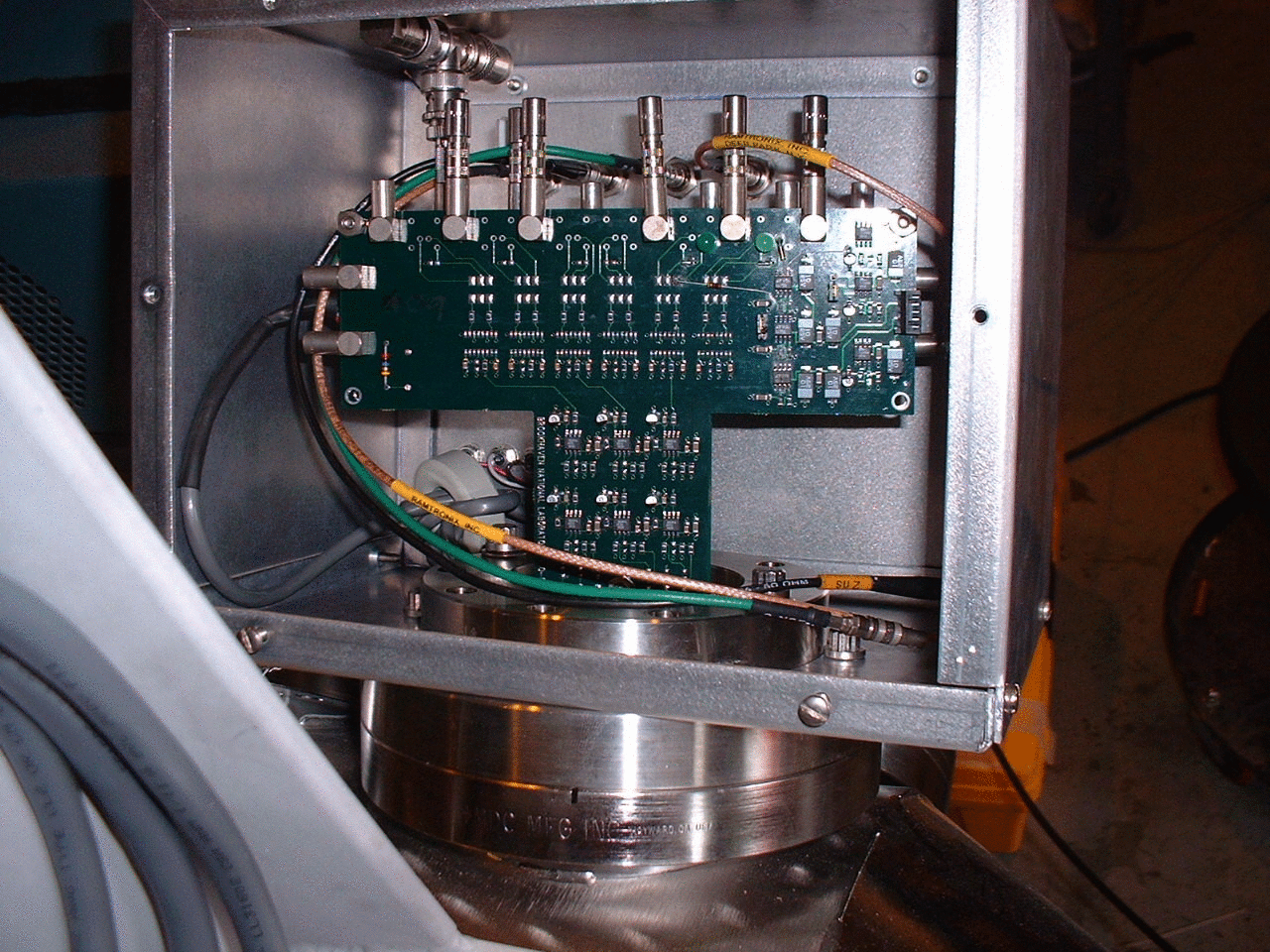
The AGS CNI polarimeter chamber has been moved to bldg. 919B for mounting the target holder and testing the drives and motors. Pictures of the motor/drive system and the target holder can be seen below.
motors/drives 1
motors/drives 2
target holder
While the technicians working on the motor/drive system for the target are completing other jobs, the chamber is available to continue the wire pulse reflection studies. John Cupolo set up the wire in the chamber again, so we could resume our tests.
Results with New Set-up
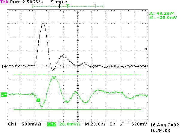
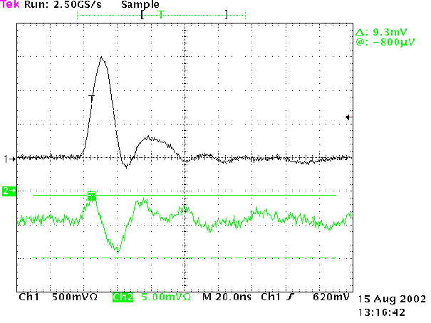
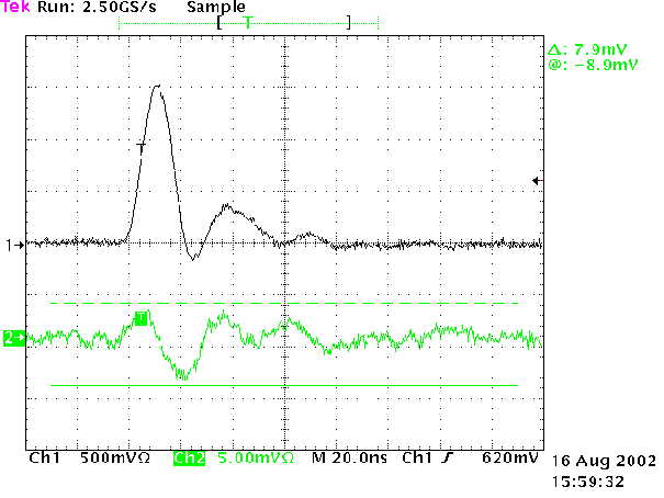
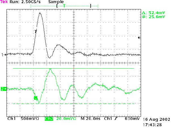
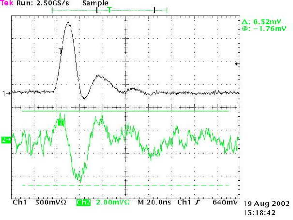
The shape of the reflection signal has changed compared to the previous test on 7/1/02. There is less ringing in the signal. Also, the refection signal now occurs at the same time as the current pulse; whereas, previously the reflection trailed the current pulse by ~15 ns.
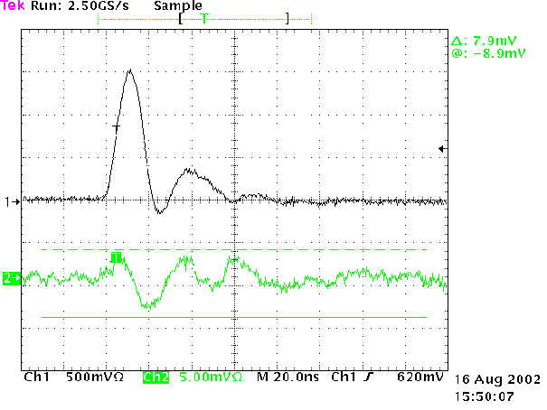
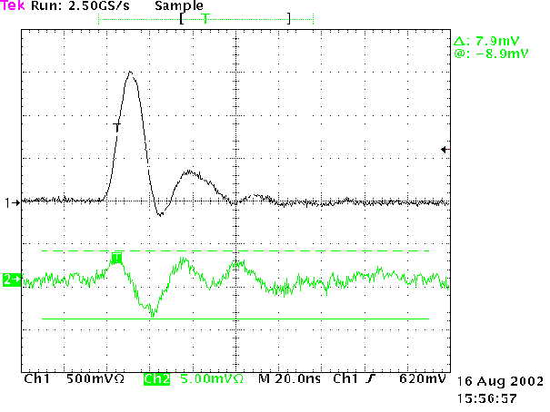
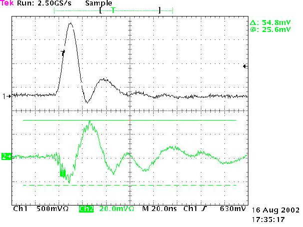
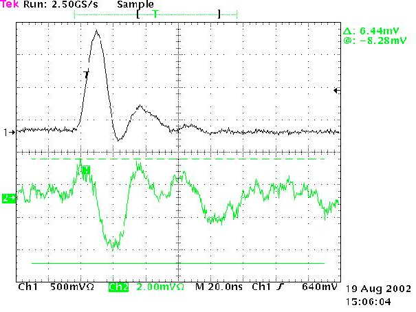
The results again show that adding the shielding box reduces the magnitude of the reflection signal. The addition of the box also flips the polarity of the signal. Compare the figures below.
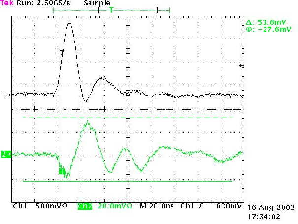
The box itself picks up the reflection signal from the current pulse. The figure below shows the signal with scope connected only to the shielding box. There was no connection to the channels from the preamp board. The signal looks similar to those above but has a smaller amplitude.
signal from shield box
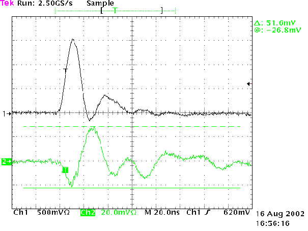
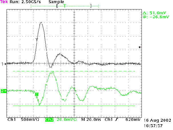
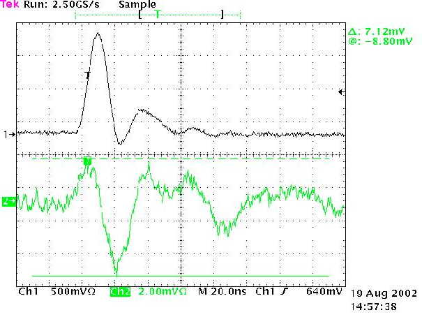
The reflection signal also persists when the low voltage power to the preamp board is removed. Below there are two channels that were read out while there was no power to the preamp board. The amplitude is slightly larger than when the preamp board is powered. The shield box was in place for these measurements (as well as the Cu mesh shielding discussed below).
ch. 6
ch. 12
Change Detector Orientation
The detector was rotated ~90 degrees, so that the strips were nearly parrallel to the beam direction.
original orientation
rotated ~90 degrees
The reflection signal was measured again. There was no noticeable change in the signal with this orientation.
Cu Mesh Detector Shielding
A copper mesh was placed on the top of the feed-through holding the detector. The purpose is to shield the detector inside of the chamber.
Cu mesh in place on feed-through
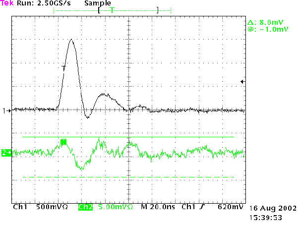
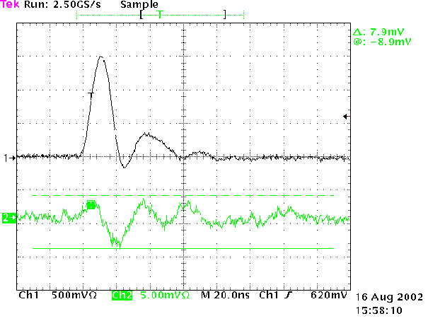
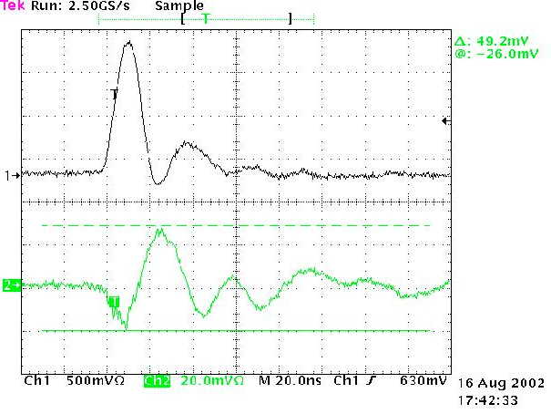
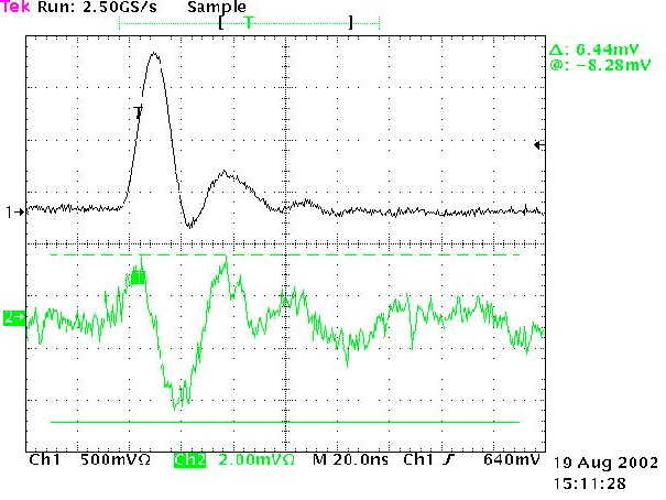
The addition of this mesh had no noticeable effect on the reflection signal. The signals shown below were measured with the detector strips oriented perpendicular to the beam direction and the shield box was in place.
ch. 1
ch. 6
ch. 7
ch. 12
maintained by: Jeff Wood, wood@physics.ucla.edu
last updated: 8/21/02