Phenix.Oncs.47.0
ONCS Data Collection Module Control Description
March 31, 1999
Ed Desmond
Summary
The following technical note describes the Data Collection System Online Controls and Interfaces to the Data Collection Module components. This technical note describes the configuration, operation , and Online Interface to the Data Collection Modules.
System Overview
The Data collection system which is addressed by this document consists of the set of Data Collection Modules (DCM), Partition Modules (PAR) and Data Collection Boards (DCB) which together are responsible for the collection, processing and distribution of event data from the PHENIX front end electronics to the PHENIX event builder.
The Data Collection Modules (DCM) consist of a Digital signal processor (DSP) , FPGA and associated support hardware. The support hardware may include a list, pedestal and threshold memory. There are 4 DCMs which reside on a single Data Collection Board (DCB). A fifth DSP performs data demultiplexing and routing. A DCB resides on a single VME board which occupies a single slot in a VME crate. There may be up to 20 DCB's per VME crate. Currently the PHENIX system calls for 98 DCBs and some 1555 DCM running in 8 separate VME crates. Each VME crate will collect data for one or more PHENIX partitions. For a detailed description of the DCM and PAR modules and their functions see the documents by Jamie Nagle, Chi , and Mickey Chiu and Chi.
Each DCM in the online system is represented by and controlled through a single software component, or object. All control functions for each DCM are accessable through this component object. Each DCM object is identified by a unique ASCII name string which is defined according to the PHENIX naming convention. The PHENIX naming convention is documented on the PHENIX ONCS Web page under the index "Conventions and Standards". All DCM components are CORBA compliant objects and thus are accessible via the CORBA interface to any remote client application which complies with this communication standard.
ONCS Software Components and Organization
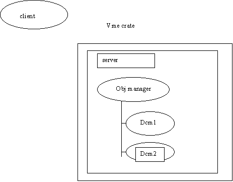
Each partition which contains DCM processors is controlled by one or more ONLINE server processes. There is one server for each VME crate that resides in the partition. If more than one partition resides in a single VME crate then that crate will contain multiple CPU modules each of which will run a single ONLINE server. Each online server contains a single software component called an object manager. This manager is responsible for the creation, deletion, and accessibility of the software objects which directly control the hardware components in the data collection system.
Each configurable and controllable component in the data collection system is controlled through a single online component object. These objects are CORBA compliant objects which reside in the online server process and are managed by the server's object manager. For the data collection system there exist objects for the data collection modules, data collection boards, and partition modules. In addition there is a set of support objects for configuring and controlling crate wide functions. As these objects contain and implement CORBA interfaces, their public methods are accessible by any remote client application to which these interface definitions are available. A diagram of these components appears below:

SYSTEM STARTUP AND CONFIGURATION
The online server process is started automatically when the VME processor is booted. The server which is loaded is contained in the startup script for the VME crate that the process resides in. VME startup scripts for all VME crates are loaded from a configuration directory which is identified by the environment variable ONLINE_CONFIGURATION. Each startup script is named according to the crate node which will execute it. Thus vme crate node iocondev8 will execute a startup script iocondev8.phenix.ppc.
Upon system startup, the online process will read a configuration file which contains a list of the components that are to be created for this partition in this crate. This configuration file is generated from a configuration file which identifies all components that are apart of an experimental run. The configuration file is contained under the main online configuration directory and in a subdirectory called Dcm. Each VME crate has a configuration file named according to the server which resides in the crate. Each component which listed in this file will be created upon system startup and placed in the INIT state.
When the ONCS server process starts up, it spawns a separate task through which all hardware access takes place. The online server process never directly accesses subsystem hardware components. This provides a measure of isolation between the online process and the subsystem software that is knowledgeable about the hardware components. The ONCS process components, execute commands on the DCM hardware by sending commands and data across a VxWorks message queue. The sub system task , sleeps on the message queue waiting for commands which are then executed on the selected DCM hardware unit. Each command returns a success/failure status to the ONCS process and optional text messages and data.
Online Interprocess Communication
As stated above the online control process which executes a Motorola Power PC processor in a VME crate, sends command and receives status information via a VxWorks message queue. There is one message queue for sending data in each direction between the Online process and the spawned hardware control process. The message sent via the message queue consists of a structure which contains a command code,
Dcm function parameters and a pointer to a data structure which is resident in global memory. The receiving process decodes the command and retrieves the required function data from the message queue.
In addition, for crate wide functions, a linked list of DCMs which are alive in this crate are made available to the hardware control process.
Run Control Interaction with the DCM functions.
Run control accesses DCM control functions by sending event messages to the VME resident ONCS task. These messages consist of data structures which contain information that is required by the DCM component. Events are sent asynchronously from the run control process to the ONCS process. Each command is verified as successful or not by a return event message. The message structure is described in the IDL file dcmEvent.idl. Its structure appears below:
Struct dcmEvent {
String sourceObjName; // source of the event
String filename; // file name for DCM data
Long unitNumber; // which dcm unit to address
String parentDcbName; // which DCB the dcm lives in
Long simulate; // flag to simulate hardware present
Long isfiledatasource; // flag to use or ignore data file
Unsigned long startaddress; // start address to write data to on DCM
Unsigned long numwrites; // number of data items to write
Unsigned long numevents; // number of events to accept
Any dcmdata; // arbitrary data structure
};
The returned message structure for each command event is defined as follows :
Struct statusMsg {
Long status;
String message;
Long srcEvtId;
};
DCM Function Description
The DCMs execute a set of functions which perform the initialization, configuration and operation of the DCMs. These functions which directly access the DCM have been provided by the Nevis group which designed the DCM. These are documented at the following Web address:
http://www.phenix.bnl.gov/project_info/electronics/dcm/dcm.html
Remote client access to the DCM functions is made available through a corresponding set of CORBA interface functions. These functions correlate one for one to the DCM hardware access functions. The CORBA functions are identified in an IDL file which resides in the directory identified by the environmental variable IDL_MAIN. These functions provide synchronous access to the DCM online component and asynchronous access via the Online event delivery mechanism. Each method interface will be described below.
The available DCM functions are listed below:
long reset(CORBA::Any dcmconfig);
long loadFPGA( const CORBA::Any &, CORBA::Environment & env);
long loadDspProgram( const CORBA::Any &, CORBA::Environment & env);
long loadListMemory(const CORBA::Any &, CORBA::Environment & env);
long loadPedMemory(const CORBA::Any &, CORBA::Environment & env);
long loadFakeData(const CORBA::Any &, CORBA::Environment & env);
long loadThresholdMemory(const CORBA::Any &, CORBA::Environment & env);
long getPedMemory(CORBA::Any &, CORBA::Environment & env);
long getThresholdMemory(CORBA::Any &, CORBA::Environment & env);
long getDataEvent(CORBA::Any &, CORBA::Environment & env);
long getSingleWord(CORBA::Any &, CORBA::Environment & env);
long getDcbStatus(CORBA::Any &, CORBA::Environment & env);
long getLinkPortStatus(CORBA::Any &, CORBA::Environment & env);
long getCompPortStatus(CORBA::Any &, CORBA::Environment & env);
long clearCompressor(CORBA::Any &, CORBA::Environment & env);
long verifyDCB(CORBA::Any &, CORBA::Environment & env);
long checkMemLoad(CORBA::Any &, CORBA::Environment & env);
long setListTest(CORBA::Any &, CORBA::Environment & env);
void takeevent(const evdata &, CORBA::Environment & env);
long getConfiguration(CORBA::Any &, CORBA::Environment & env);
void getUnitNumber(CORBA::Any &, CORBA::Environment & env);
void getRunStatus(CORBA::Any &, CORBA::Environment & env);
PARTITION MODULE FUNCTIONS
PAR_reset( CORBA::Any & parConfig );
PAR_online(CORBA:: long vmeslotaddress );
void checkBusy(CORBA::any & parConfig);
void getParStatus(CORBA::any & parConfig );
void start(CORBA::Long & unitNumber);
void getBusyOnline(CORBA::any & parConfig );
void loadLevel1Data(const CORBA::any & parConfig );
void loadFakeData( const CORBA::any & parConfig );
CRATE WIDE FUNCTIONS
DCM_startReady( );
DCM_startRun( )
DCM Component Description
The DCM components are considered to be by the Online system to be active components. That is they are components that can execute or perform some action.
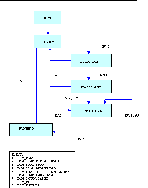
All active components in the ONCS system execute actions in one of a set of finite states. Functions are executed with these states as a result of receiving an event which results in the transition of the component into one of its finite states. The following tables describe the set of states and events through which the DCM components execute.
DCM Finite State Transitions
The following table and diagram describes the different states and transitions between states that a data collection module (DCM) may transition through.
DCM Finite State Transitions
The following table and diagram describes the different states and transitions between states that a data collection module (DCM) may transition through.
|
State |
Event |
Destination State |
|
Idle |
DCM_RESET |
Reset |
|
RESET |
DCM_LOAD_DSP_PROGRAM |
DSPLOADED |
|
DSPLOADED |
DCM_LOAD_FPGA |
FPGALOADED |
|
FPGALOADED |
DCM_LOAD_LIST_MEMORY |
DOWNLOADING |
|
DOWNLOADING |
DCM_LOAD_THRESHOLD MEMORY |
DOWNLOADING |
|
DOWNLOADING |
DCM_LOAD_FAKEDATA |
DOWNLOADING |
|
DOWNLOADING |
DCM_DOWNLOADED |
DOWNLOADING |
|
DOWNLOADING |
DCM_LOAD_PEDMEMORY |
DOWNLOADING |
|
DOWNLOADING |
DCM_LOAD_PEDMEMORY |
DOWNLOADING |
|
DOWNLOADING |
DCM_LOAD_THRESHOLD MEMORY |
DOWNLOADING |
|
DOWNLOADING |
DCM_LOAD_FAKEDATA |
DOWNLOADING |
|
DOWNLOADING |
DCM_DOWNLOADED |
DOWNLOADING |
|
DOWNLOADING |
DCM_RUN |
RUNNING |
|
DOWNLOADING |
DCM_RESET |
Reset |
|
RUNNING |
DCM_RESET |
Reset |
|
RUNNING |
DCM_ENDRUN |
DOWNLOADING |
State
|
|
IDLE |
RESET |
DSPloaded |
fpgaloaded |
Downloading |
running |
|
IDLE |
|
reset |
|
|
|
|
|
RESET |
|
reset |
loaddsp |
|
|
|
|
dsploaded |
|
reset |
|
loadfpga |
|
|
|
fpgaloaded |
|
reset |
|
|
LLM,LPM, LTM,LFD, DL |
|
|
downloading |
|
reset |
|
|
LLM,LPM, LTM,LFD, DL |
RUN |
|
|
|
|
|
|
|
|
|
RUNNING |
|
reset |
|
|
ENDRUN |
|
DCM State Transition Diagram

DCM Control Application Description
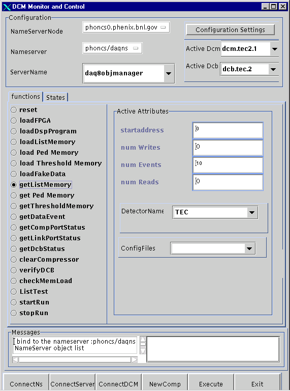
A Java application exists to access and invoke functions on any DCM which is currently active in the Online system. The application also allows new DCM components to be added at run-time. DCMs can be configured and their functions executed from the application. The application can run in any platform which supports a Java Virtual Machine.
Access to the Data Collection Modules is available through a client application which is available on phoncs0. This application is access by executing the "dcmviewer " script which is in the phoncs account bin directory. This directory is defined by the environment variable "SCRIPTS_BIN". Execute the application by calling "$SCRIPTS_BIN/dcmviewer".
The user accesses individual DCM components by selecting a server to address. A list of all available servers which are known to the ONCS system will be displayed upon the application startup. This application uses the default nameserver which contains a list of all active servers. This defaults to "phoncs/daqns". This selection can be changed by clicking on the ConnectNs button.
Select a Server which is contained in the list in the ServerName fields by clicking on it. Then connect to this server by clicking on the button labeled "ConnectServer". Then select a DCM from the list of known DCMs in the selected server from the list labeled "Active Dcm. Press the button labeled "ConnectDCM" to connect to that DCM. Once this is done the available functions for a DCM are selected from the list in the "functions" tab panel. Select a function and press the "Execute" button to execute the command.
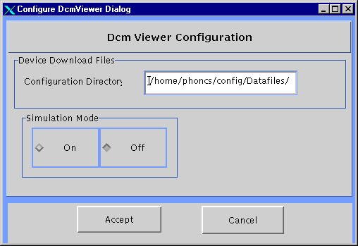
Available configuration files are selected by pressing the "Configuration Settings" button. This pops up a Configuration dialog box which contains an entry field for the desired directory. The new directory is read and its contents are displayed in the main application frame when the button labeled "Accept" is pressed. The configuration directory defaults to the currently displayed directory.
The application can be run in simulate mode in which all functions are simulated in that all command functions are executed up to the point where the actual hardware component is accessed. This mode of operation is used to test ONCS software connections.
The application user interface is shown below

Dcmviewer Configuration Dialog Box

Diagnostic Dialog Boxes
The DCM user application can display diagnostic information which is read from the data collection module. The diagnostic displays include Compressor, LinkPort and Dcb status.