I put this together to answer a question for Adam, but it may help clarify some points I was trying to make this morning:
This is a clarification of why (at the moment) I think that the preshower ADC mapping test that has been tried will not be distorted effects such as pedestal drift
I did not use the preshower pedestal table as I thought that it is probably risky on this data. For example, I could not match my pedestal fits from the data without tracking, to this data with tracking.
The RMS value is quite different, on average, in the preshower swaps, but it is not only the value but a pattern that emerges, (Note: a cut with the adc values greater than 0 has been made for this method to work)
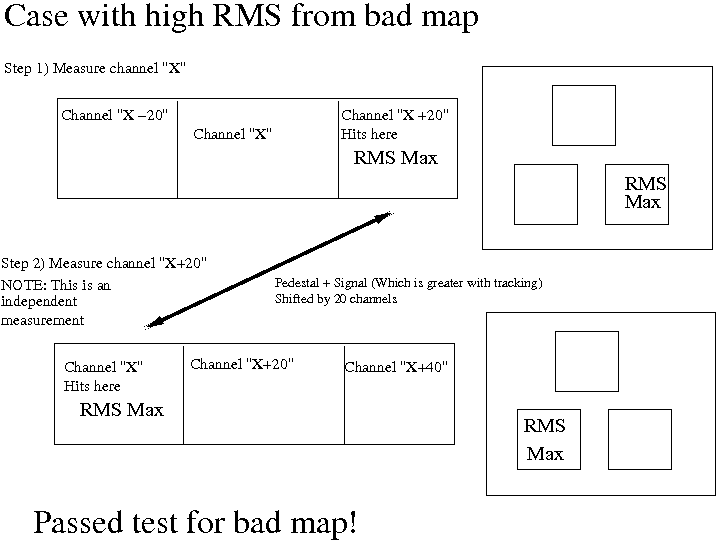
We have, per channel, hits from sub-modules either side recorded as well. If we looked at one channel and the sub-mods either side, then the high rms in neighbouring channel is a pretty loose selection for a mapping problem.
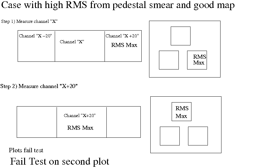
However, another condition is added on top of this. When one of these high RMS channels are found, we look back 20 channels, to an independent measurement of a new channel, "X" say and its neighbours "X+/-20" and look in the "X+20" channel, if the RMS is higher here the mapping is flagged as a possible problem.
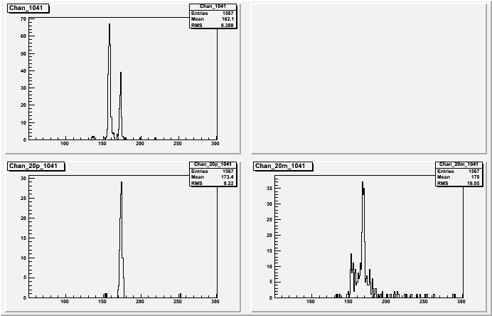
Let me give you an example of how robust this seems, I have cases where I have double pedestals where it picked out a reasonable mapping candidates, see for example:
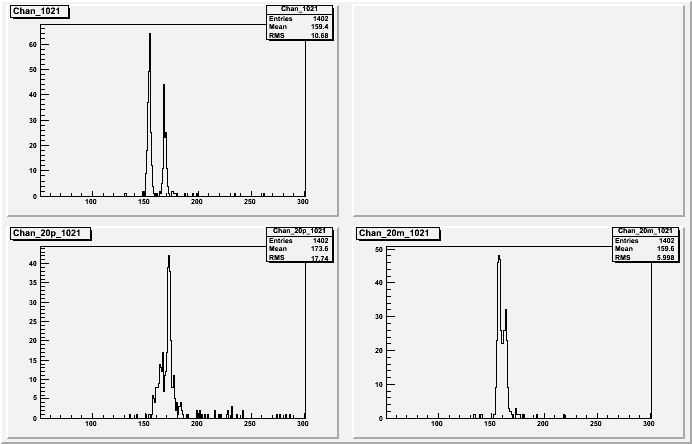
Here the pedestals are strongly double peaked but on inspection there is a strong shift of what could be physics events in the "-" plot for 1041, this was seen in channel 1021. Moving to the plot for 1021 this moves to the "+" plot. Note that the two summary plots (1041, +/-20) and (1021, +/-20) are made independently from each other
There is a further point I should mention. In a plot of a channel, there are three plots, the top one for the channel then the lower two for the +20 and -20 channels. Note that in these plots the number of entries are all identical. Each of these plots is equally normalised. If an events on a plot were recording just pedestal, they will fall tightly in a Gaussian. However if some of them are physics, they will fall outside the Gaussian. As the number of entries in each plot are normalised, these non Gaussian events will smear the final peak and distort the RMS of the plot.
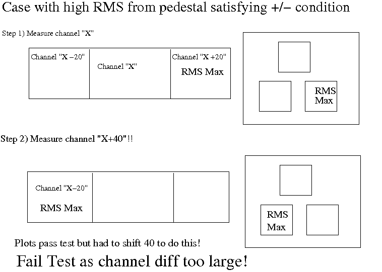
So why not worry about smearing from pedestal drift? This is a slightly complex answer to that question but I will say here that it is because, if the mapping were good, and we wanted to satisfy the condition that a positive plot had a high RMS and a negative plot had a high RMS, we would have to step back 40 channels to satisfy this condition, not 20. The distance between the two 20 channel offsets in the measurements (if the mapping is good), will require this 40 channel difference. For a bad mapping we would only step back only 20, as this is the distance between the crossed over channels
A picture is work a thousand words, so I made some sketches to show what I am aiming at
I would conclude at this stage that smearing should not give a false positive in the test but would likely reduce the efficiency of finding bad maps. Other non-mapping effects should suffer the same fate, they would show up as +/-40 channels thefore only decreasing the resolution of finding bad maps, not, however, giving false positive swaps.
OK, here are three examples, the first with bad mapping (passes test), the second with a pedestal drift smear (fails test), the third with how a pedestal drift would only pass if we step back 40 channels so this will never give a positive either
____________________________
____________________________