SVT CABLING PROCEDURE
FROM YEAR 2002
This page contains a description of the procedure for connecting Silicon
Vertex Tracker (SVT) with the outer cone. This procedure is based on the
experience from year 2002 run, also all graphical documentation is from
August 2002. Click, please, on the thumbnail pictures to get the full size
originals.
Content:
-
TempFlex cables
-
Low and high-high voltage cables
-
High-low voltage cables
-
Water testing
-
SVT shield
- SSD installation
- Outer shield
TempFlex cables
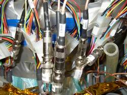
The first cables to connect are the TempFlex cables. Their connectors need to be pressed together tight, if they are even little
bit loose some of the pins may get disconnected. This can happen also during
any manipulations. For this reason it's good to secure the connectors by
a vinyl tape. The tape should not however press too much on the releasing
flaps of the connector.
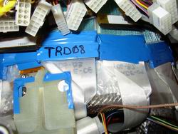 tape-secured connector
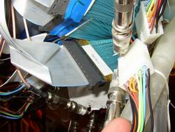
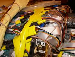
There are some sharp objects close the TempFlex cables like the SSD
and SVT holders, and the metal mesh, which is cut around the SVT holders.
Like in the picture above, it's generally good idea to cover these places
,if possible, with a tape.
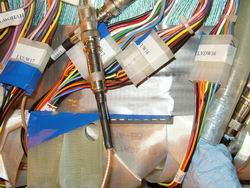
WATCH OUT!!
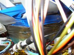
At the west side at the
bottom of the cone TempFlex cable TRUW11 is twisted somewhere inside of
the cone. The connector is little worn off so that the cable can be connected
both ways. Attention needs to be paid to connect it right.
 twisted
cable
twisted
cable
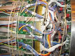
Since most of the cables
in the cone had shifted toward the bottom of the cone, it is necessary
to try, when connecting the cables, to position them as high as possible
on the cone in order to achieve as low overall profile as possible.
Since the cables slide back to the bottom it's necessary to use the vinyl
tape to hold the cables in places every time after placing a bunch of cables.
Since the tape is sticky and it would be hard to remove it from the cables,
it's good to try to put it only over the plastic connectors.
North-East top
 |
North-East mid
 |
North-East lower mid
 |
South-East mid
 |
After the TempFlex connectors
are in place it is the best time to connect the LV connectors and check the connections with the portable
SVT lab. At this point the possible bad connectors are easily reachable
if needed. From this point the connectors will not be moved any
more.
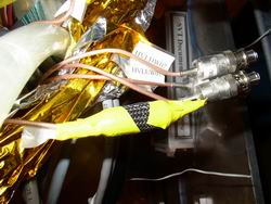
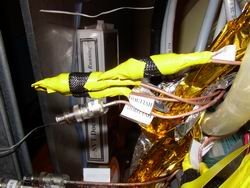
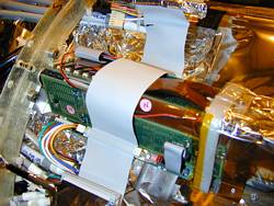
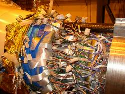
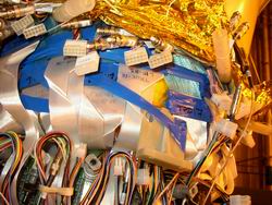
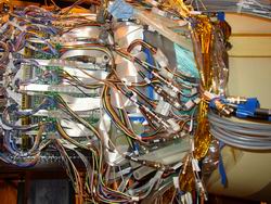
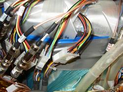
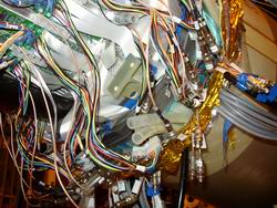
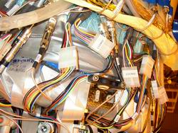
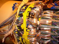
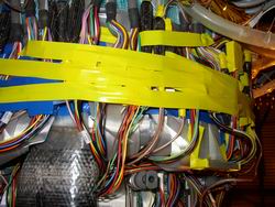
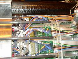
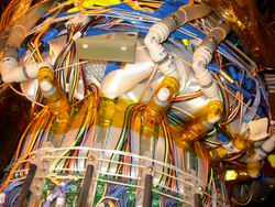
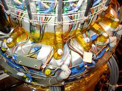
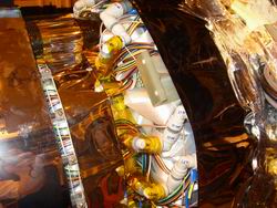
Since the TempFlex cables are fragile and some of
the other connectors that lay on them (especially LV connectors) have sharp
edges, we covered the TempFlexes by a single layer of a protective tape
. The testing of connections can be also done at this point. Following
pictures show SVT after the TempFlexes were connected and protected by
a tape with LV and HV cables connected for testing purposes.
North-West mid
 |
North-West mid
 |
North-West mid detail
 |
North-West upper mid even greater detail, note the taped edges of LV connectors
 |
North-West lower mid
even greater detail
 |
North-West bottom
 |
North-West bottom
detail
 |
South-West mid
 |
South-West top !!!SSD support!!!
 |
South-West bottom
 |
South-West bottom
 |
|
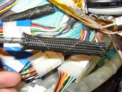
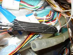
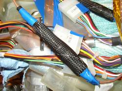
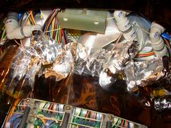
Low and high-high voltage cables
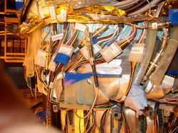
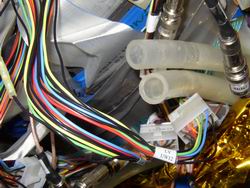
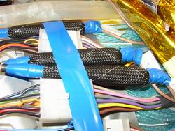
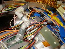
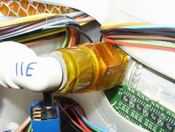
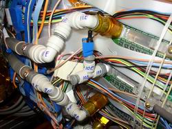
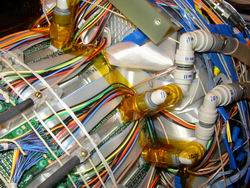
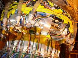
In the year 2002 new material for insulation HVH connectors was used. Following
three pictures show how the isolation was done. So far the best seems to
use a cable tie on a side closer to the cone and a vinyl tape on both ends.
The cable tie has a tendency to slide off the hose, for this reason we
need to use the tape on both sides. Using only tape without a cable tie
doesn't work.
As well as for LV cables the best way is to start from the top of the
cone trying to position the cables as high as possible in order to create
more space on the bottom of the cone, where are all the collapsed cables
(especially on the east side). The LV connectors should lay on the protective
tape in order not accidentally damage the TempFlex cables. Should the LV
connectors lay on the bare cables it's better to put a tape on them. Every
time a couple of cables is positioned they are secured in the place
by a tape.
North-West top
 |
North-West top detail
 |
South-West top
 |
South-West mid
 |
South-West bottom
 |
|
High-low voltage cables
In the year 2002 run HVL cables were not used, they were removed from transition
boards. Only connectors coming from the cone had to be taken care
of. They were insulated using only the tubes and vinyl tape and put in
remaining free places - usually stuffed back under the cone.
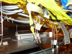
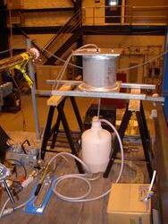
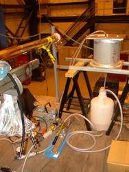
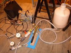
Water testing
Following pictures show the water setup used for testing SVT cooling system.
SVT shield
Preparation
In order for shield to be low and smooth everything has to be kept as low
as possible. This includes the hoses from the cooling system that are between
the water manifold and cone and also between the SVT ladders and water
manifold. Another thing that has to be kept low are cables coming from
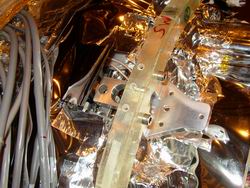
the transition boards. For all this we used cords on different locations.
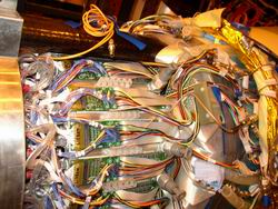
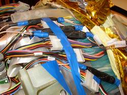
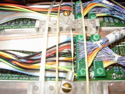
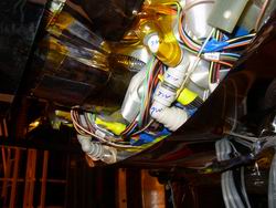
The first picture shows four cords used on the cone. Two cords are
used to hold down and secure LV and HVL connectors in case that the vinyl
tape dries out. Other two cords are holding down water hoses and water fittings.
On the picture the cord holding elbow fittings goes above the SSD support,
it was however latter agreed that this cord should go below the SSD support!
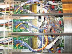
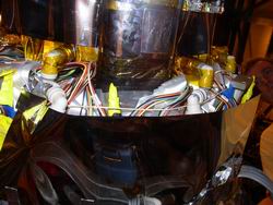
Other two pictures show cords going trough and above the holders for carbon
bars. There are two cords going through two different holes in the holders.
The first cord going trough the first hole is used to press down the cables
close to the transition boards in order to increase heat transfer from
the transition boards. This however puts some upward pressure on the holders
which can cause them to pop off. All the other cords are used to secure
the holders in place.
North-West top
 |
North-West top
 |
North-East shield support - detail
 |
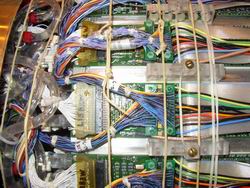
Next three pictures show how were added other cords that hold down cables
and hoses between transition boards and SVT ladders.
North-East mid
 |
North-West upper mid
 |
North-East upper mid
 |
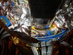
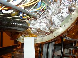
Insulation
Since on some places a conductive tape will be used for shielding, places
on which it could short to the water manifold have to be insulated. The
procedure is shown on the following pictures. First are insulated the water
fittings and later the transition boards and water manifold. Also the two
main SVT carbon bars should be insulated.
North-East
 |
North-East mid
 |
North-West top
 |
North-West top
 |
North-West bottom
 |
South-West top
 |
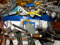
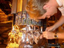
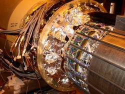
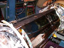
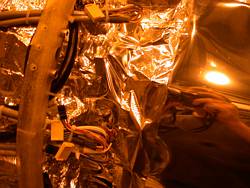
Shielding
As first two stripes of .003" aluminized mylar are used on the places where the shield will
not be folded - on the cone and on the transition boards.
North-West top
 |
North-West mid
 |
North-West bottom
 |
West bottom
 |
North
 |
|
Next step is to connect these two stripes by a conductive tape going
as low as possible. As first are covered the water fittings by a single
stripe, as shown in the first picture. Remaining empty places between these
stripes are covered by small pieces of the conductive tape. The last part
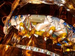
is to connect this shield to the shield in the cone. It's important to
leave holes in the shield at the places of SSD supports. The last couple
pictures show SVT with mounted SSD ring and positioned SSD cables. At this
point is the detector is ready for removing the hard case and putting on
the soft shield.
North-West top
 |
North-East mid
 |
East bottom
 |
North-West mid
 |
South-West
 |
South-West top !!!SSD
support!!!
 |
South-West bottom
 |
South-East bottom
 |
North-West
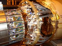 |
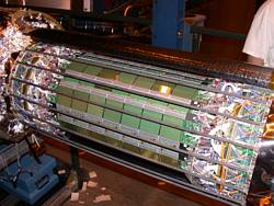
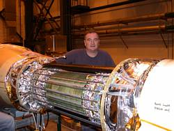
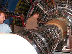
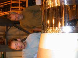
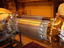
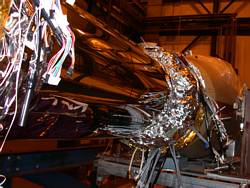
At this point cabling and water inlets are shielded. The last thing that has to
be shielded is the main body of the detector, which was so far protected by the
hard case. The first step is thus to remove the hard case, which means first
removing the carbon bars then removing the hard case itself and then again
putting back the carbon bars. This part is one of the most dangerous since the
detector is not protected at all during the manipulation. The following pictures
show the detector after the hard case has been removed and the supporting bars
were put back in place
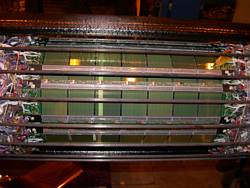
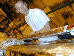
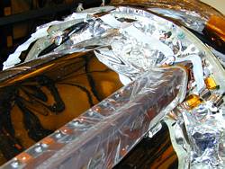
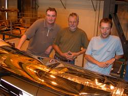
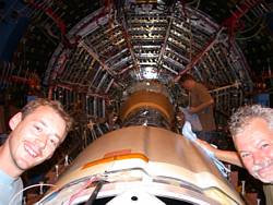
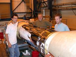
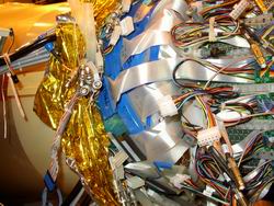
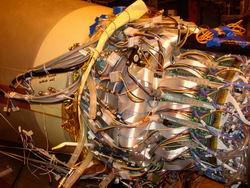
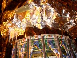
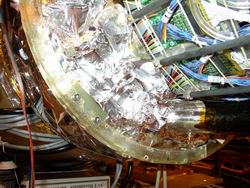
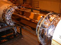
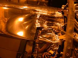
The shield of the main body
of the detector is made of one piece of aluminized mylar. The mylar is wrapped
around the detector and connected on the bottom. It's preferable to connect
the mylar at the bottom, this prevents the shield from sliding off the detector
in case the connecting tape gets loose. First three pictures show the mylar
wrapped around the detector. On the next three pictures is shown how it is connected
to the rest of the shield using the conductive tape.
North-West
 |
North-East
 |
East
 |
West
 |
East
 |
South-West
 |
SSD installation
After the main body of SVT is shielded the SSD
is mounted on the SSD support rings. For year 2002 run only one ladder of SSD
was tested. This work is done by the SSD group.
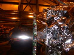
Outer shield
After the installation of SSD the outer shield has to be added. As shown
in the following three pictures it's made of three parts connected by the conductive
tape. There are two stripes covering electronics- one on each side and a big
piece covering the rest of the detector. This whole shield is connected to the
conductive surface of the cone by a conductive tape.
After this, it's all DONE....